
Mass Production of Bent Stories
To efficiently build a large trestle such as this, I will take advantage of the many identical assemblies of bent stories. Of the 20 bents, four are less than full height. I’ll handle exceptions like those individually. In this article I will describe how I build the bent stories in batches. These will be 16 top stories (with 5/8” x 11/16” cap) and 6 second stories.
CAD Drawings
LibreCAD is used to draw the construction plans. It is a free open-source CAD program that is relatively full-featured for 2D drawing. The learning curve is a bit steep, but I find it invaluable to get a good, accurately measured drawing.
Link: http://librecad.org/cms/home.html
User Manual: http://wiki.librecad.org/index.php/LibreCAD_users_Manual

Figure 1 Bent Top

Figure 2 Bent Second
Figures 1 and 2 are (not to scale) plans for the top and second bent stories. There are many of these that are identical, so producing them in a batch makes sense. I had a few drawings printed full-size (18”x24”) through Staples to use during construction. (At the bottom of this post are links to the DXF and PDF files.)
Link: http://www.staples.com/sbd/content/copyandprint/engineering-prints.html
Assemble materials
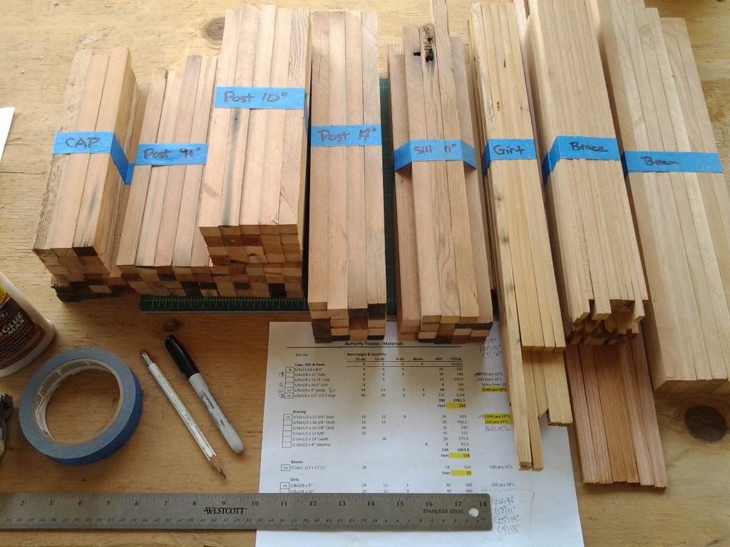
Photo 1 Material
I first ripped the materials needed so I could do a whole run of many bents without interruption. Photo 1 shows my supply during production, and the spreadsheet I used to track how much of each size and length I would need. I need a LOT more than what is shown, but I have enough to start producing bents.
I used a spreadsheet to keep track of how many pieces of each size wood I needed. I’m going to do the 15 Top and 6 Second stories in a batch. The others are all unique sizes that I will leave for later. For the top story there are (15) 5/8” x 11/16” x 8 ½” Caps, (30) 5/8” x 5/8” x 9+” vertical posts (leave them just a bit long) and (30) 5/8” x 5/8” x 9 ½” angled posts (3-in-12 batter, or 14.0 degree angle). The second story will need (6) 5/8” x 5/8” x 11” sills (at the top), (24) 5/8” x 5/8” x 9” vertical posts and (48) 5/8” x 5/8” x 9 ½” angled posts.
Construction jigs

Photo 2 Gluing
Post jig – This is used to glue the cap or top sill and attached posts. It is positioned with the bottom of the posts at the edge of the jig so a table saw can be used to even the bottom up for a perfect fit onto the next story assembly or the mud sill. Photo 2 is a saw jig being used for gluing posts.

Photo 3 Saw Jig
Photo 3 shows a Saw Jig in place on the table saw. Note that the blade guard was raised for the photo, but was in place during cutting!

Photo 4 Brace Jig
Brace jig –Braces as seen from behind are top-left to lower-right, so when they are viewed from the front of a bent are top-right to bottom-left. Photo 4 shows the Brace Jig in use. The brace being glued is placed on the jig, dots of glue applied and the bent is set on top of that and weighted.
Glue the paper plans to plywood, for example, one plan with the bottoms of the posts at the very bottom of the jig to use on the table saw to evenly trim the posts, and another to be used for brace gluing and bent assembly. I attached a strip of plastic using a glue stick where the posts meet the cap, so the glue won’t stick to the paper. (It is not visible in the photo because it is clear.) For the braces, I add brace scraps under the posts so the bent sits level during the gluing process.
Production

Photo 5 Stories
So working from saw jig to saw to brace jig, glue the posts to the cap or sill, then the brace on one side, then a brace on the second side. I let the glue set for about 1 hour before moving on to the next step, so the mass production process is a few small steps spaced apart by a bit of time. (20-20 hindsight made me realize that braces could have been glued twice as fast if I had positioned the saw jig guides so that it could also be used for braces.) Photo 5 shows the result of a few days of work.
Tip: You will need clamps for posts and gluing weights for sway braces. For weights, I use a combination of small snack-size bags filled with sand and a couple of old gallon pails about half full of sand.
To finish construction, drill a pilot hole through the cap or sill into each post and drive a 1 ¼” finishing nail into that for extra strength. Each brace should also be nailed to each post it crosses.
Next time: Odd-size Stories and Bent Assemblies.
What is Batter?
Batter is the amount of offset in the angled posts expressed as feet offset per 12 feet in height, so 3-in-12 would mean 3 feet horizontal offset for each 12 feet in height. The Rio Grande Southern typically used 2-in-12 batter for tangent (straight) trestles, 3-in-12 for curved and 2½-in-12 for combination trestles. Since this trestle is curved, it uses a 3-in-12 batter. The angle to use on a miter saw is 14.0 degrees.
Note: If you want a different angle, the conversion from batter to degrees is angle = tan-1 batter, where batter is expressed as a decimal, so 3-in-12 = 3/12 = 0.25. For example, a 2-in-12 batter would give an angle of tan-1 (2 / 12) = tan-1 0.16666 = 9.46 degrees. Or, here you go:
| Batter to Angle | |
| Batter (in 12) | Angle (deg) |
| 1 | 4.8 |
| 1.5 | 7.1 |
| 2 | 9.5 |
| 2.5 | 11.8 |
| 3 | 14.0 |
| 3.5 | 16.3 |
| 4 | 18.4 |
Drawings of bents, 3-in-12 batter, 1:20.3 scale. The PDF files are designed for printing on 18″x24″ paper.
| Drawing | DXF | |
| Top Story | DXF | |
| Second Story | DXF | |
| Third Story | DXF |


