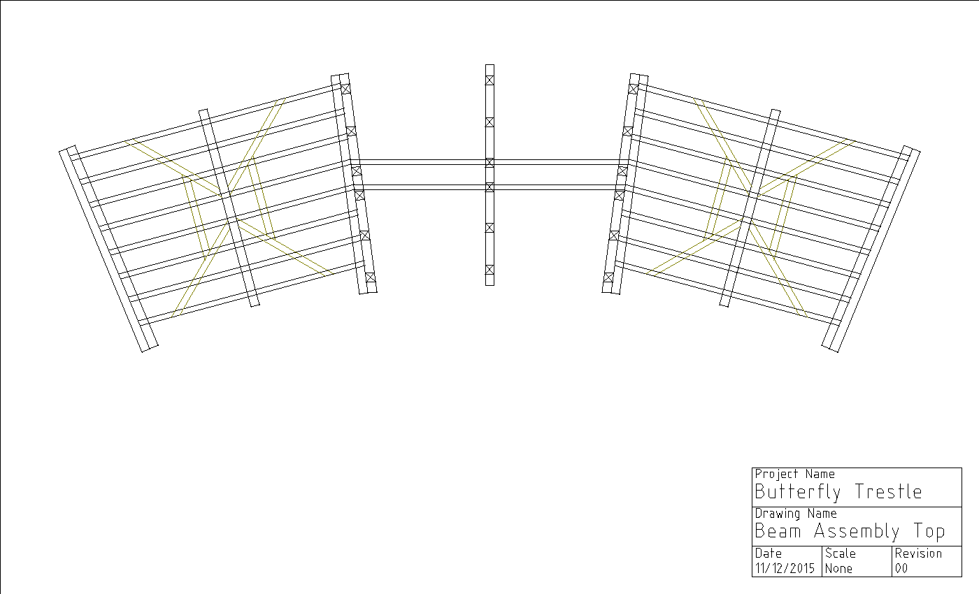
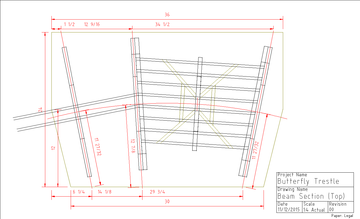
Building a Large Curved Trestle on a Grade – Part 6

Assembling a Trestle Section

Construction Jig

To accurately position the bents I created a construction jig. I created a full-size CAD drawing that I had printed at Staples as shown in Figure 1. The bottom view is the one I will use to position the bents properly, as I am building this “upside-down,” much like you’d do in a smaller scale. The drawing is “glued” to a piece of plywood with wheat paste (flour and water) and stops are added at each bent location as shown in Photo 1. I added two protruding nails to each to allow a rubber-band to wrap around and hold the bent tight against the stop.

Figure 1 - Bent Stringer Plan

Figure 1 – Bent Stringer Plan


Photo 1 - Bent Assembly Jig

Photo 1 – Bent Assembly Jig

If you want to draw the diagram – and you really only need a center line and lines for each bent – you can lay this out with the tried-and-true string compass method. (The red lines are what you would draw.) To calculate the span between bents in inches, which will give you the desired angle in degrees between each pair of bents, use this formula (diameter in feet): span = angle * diameter / 9.55. For example: 6 foot radius (12 foot diameter), 7.5 degree angle, span = 7.5 * 12 / 9.55 = 9.424 (just under 9 7/16”).

Bent Angle Supports

Trestle bents are always vertical, so there will be an angle other than 90 degrees between the stringers and the bents. On a 2.5% grade, the angle is a 1.43 degree lean toward the downhill end if building upside-down. (This is the same angle as the 2.5% grade is from horizontal.) To create an angle guide to use during construction use a piece of rectangular material such as thin plywood and measure along an edge 20”, where the angle is offset ½” from square. To find the distance to any rise for any grade, use distance = rise / grade. So for a ½” rise on a 2.5% grade, distance = 0.5 / 0.025 = 20”.

I made several identical plywood angle guides by building an angle jig to hold a rectangular piece at the correct angle when run through the table saw as shown in Photo 2. I added scrap cedar nailed and glued in place to provide a clamping surface. The jigs ready for use are shown in Photo 3.

Photo 2 - Bent Angle Jig

Photo 2 – Bent Angle Jig


Photo 3 - Angle Jigs

Photo 3 – Angle Jigs

Section Assembly

I positioned bents 15 through 18 on the assembly jig as shown in Photo 4. The girts must be added “upside down.” So unlike the conventional assembly method, I’ll need clamps to hold them in place while the glue sets. (I will need more clamps!) After the girts are in place, wall bracing is added between these four bents. (I use a small piece of brace material where the bent is on the outside surface of the pair to prevent excessive bending as shown in Photo 5.

Photo 4 - Bent Assembly Fixture

Photo 4 – Bent Assembly Fixture


Photo 5 - Small Block Under Top Brace

Photo 5 – Small Block Under Top Brace

The complete assembly of bents with girts and wall bracing is shown in Photo 6.

Photo 6 - Complete Assembly

Photo 6 – Complete Assembly

Building a Large Curved Trestle on a Grade – Part 5

Part 5 – Building the Beam Assemblies

The Beam Assemblies

There are two beam assemblies each made of eight 3/8” x 1½” beams spaced equally with angled braces as shown in Figure 1. These rest on short bents attached to a full-height bent. Bents #8 and #12 rest on these beams. Two additional beams run between the main assemblies, running through bent #10.

Figure 1 Beam Assembly

Figure 1 Beam Assembly

As there are only two of these I will not build a jig. Each beam has a 7.5-degree angle at each end, matching the bent angle. A full-size paper plan was glued to acrylic with a washable glue stick to keep it flat. The cuts are measured directly from the plan by putting a beam in place and marking the location. I also used some ½” square stock cut at the same angle for blocks to reinforce the beams and provide attachment points to the support bents. Photo 1 shows beams and blocks on the plan.

Photo 1 Beams and Blocks

Photo 1 Beams and Blocks

The beams and blocks are first glued in pairs, then the pairs are glued and finally the two halves are joined as shown in Photo 2.

The beam assemblies were then glued and nailed to the support bents. Note that the beams are NOT square to the bents – the bents are square to the workbench. Finally, the bent resting on the beams (also not square to the beams) is glued.

Photo 2 Beam Assembly

Photo 2 Beam Assembly

Adding Girts

Photo 3 Bent 7, 8 and 9 Assembly

Photo 3 Bent 7, 8 and 9 Assembly

Following RGS practice (on this bridge), there is 1 girt in the center and 1 near each end of every sill except the mud sills. So there will be 3 girts per story between each pair of bents. Because this bridge is curved, every girt will have angled ends (3.75 degrees), and mostly different lengths. The ends of each girt is notched a bit to better hold the bent in position. To accurately measure the length, a 3/8” square girt is positioned completely covering one sill, and marked where it crosses the other sill. I used a mini-hacksaw to cut a slit 5/16” from each end and a hobby knife to make a vertical cut. A quick pass with sandpaper finishes the notch. In theory, I should be able to mass-produce each size I need, but in practice I’ll not be surprised if each one is unique.

Figure 2 Beam Detail

Figure 2 Beam Detail

This assembly is fairly rigid. The bent 7, 8 and 9 assembly is shown in Photo 3.

Cement Board Base

Figure 3 Base Layout

Figure 3 Base Layout

Transfer plan Figure 3 to 2’ x 3’ cement boards. Use rip

ped Trex 2×6 for footings glued down with Gorilla Glue. Before gluing footings, use the lines to locate and drill holes from the top for screws driven from the bottom to secure the footings. Drill holes in the mud sill and the Trex for brass pins. Photo 4 shows the base after gluing and screwing the Trex footings.

Beam Assemblies

Photo 5 shows the two complete beam sections ready for assembly in the railway. Photo 6 shows the prototype bridge beam sections.

Photo 5 Beam Sections

Photo 5 Beam Sections

Photo 6 Prototype

Photo 6 Prototype

Weekend Project

This Memorial Day weekend, I did a small, non-train project. I made a planter box plus an old bed headboard that we had on hand. It went pretty well, in spite of the fact I had no plan. (I should have had a plan.) Here is the basic box-planter. This was built with less than $25 of materials; all cheap cedar fence boards.

Planter before adding plastic liner and soil.

Top trim detail

My first attempt at angled corner trim. It went well.

Finished and planted!

Here it is with soil and plants. My wife loves it. ‘Nuff said?

Cedar Planter Instructions

Materials:

  • (10) 5/8″x5 1/2″ x 5-foot Cedar Fence Pickets (not dog-eared)
  • (1) 5/8″x5 1/2″ x 6-foot Cedar Fence Picket (good quality)
  • Box of 1 1/4″ Finishing Nails
  • Exterior wood glue (Tite Bond 3 recommended)

Tools:

  • Table Saw
  • Speed Square
  • Hammer

Directions:

If the material is of poor quality, get an extra 5-foot board or two to account for huge knots and/or damaged boards. The 5-foot pickets were less than 2$ at Lowe’s and the 6-foot picket was just over $2.

Pick your best two 5-foot pickets to be the front and the next-best three for the back and ends. Use the poorest quality three to make the bottom. The remaining pickets will be ripped into 2 ½” stock for the braces and legs. The 6-foot pickets will be ripped into 1 ½” widths for the top trim.

Rip 3 Boards for the bottom, two 5″ wide and one 4″ wide all cut to 58 3/4″ length. Cut four 2 ½” x 14″ braces, assemble the center T-brace with nails and glue, and nail and glue the braces in place onto the bottom boards. Definitely use a square to make sure this is an accurate rectangle!

For the sides and ends, rip 5 pickets to 5” width. (I did this because 1 edge is typically not in good shape and about 9” deep is fine for planting.) Cut one into four 14” pieces. Use the 2 ½” stock to make the ten 16” leg pieces. Glue and nail the legs to make two end assemblies and two side assemblies.

Put the base on its side, and attach the end pieces with glue and nails. (Use some scraps to prop the bottom up 5/8”.) Then attach one side piece in place, flip the structure and attach the second.

I cut more 2 ½” stock to make three layers of additional support for the bottom, glued behind the legs, essentially making a laminated post at the corners and center.

Rip the 6-foot picket into three 1 ½” strips for the trim. Position each piece on the box with the edge flush with the box inner edge and mark where the angle cuts are to be made. Work carefully and fit each piece.

You may wish to finish this with a colored or clear stain, or leave it to weather to a gray shade. I left my planter natural.

Construction Drawing (PDF): Cedar Planter


Building a Large Curved Trestle on a Grade – Part 4

Odd-sized Stories and Bent Assemblies

After a break for the Holidays and the generally unpleasant freezing weather, I’m back at it. In this installment, I’ll be building the odd-sized stories, adding the mud sills and assembling complete bents.

A spreadsheet was used to calculate the height of the bottom story for each bent, as I’m building the terrain to fit the bridge. If you are fitting a bridge into existing terrain, you would measure the total height and use that to calculate the required stories.

Bent Calculation

To calculate the required heights, I’ll use a bent that is 26 13/32” tall as an example. The top story is 9 11/16” tall not including the bottom sill, the second story is 9 5/8” tall, so the third story height is:

Height = 26 13/32 – 9 11/16 – 9 58 = 7 3/32”

Allowing for the bottom sill, the third story post assembly should be cut to the bent height less the mud sill height:

Cut Length = 7 3/32 – 5/8 = 6 15/32”

(Note that the calculations are to the nearest 1/32”, but I doubt that level of precision can be achieved in practice. Shims and/or sanding will be used to adjust heights if needed.)

Odd-sized Stories

All of the third stories, and many of the top and second stories, are not full height. The posts will be glued in place before cutting. Then a rubberized push block will be used for sawing the odd-sized stories to even the posts. The friction will help prevent the posts from flexing when run through the saw. I made a brace using scraps to hold the posts in place, but that didn’t seem necessary. I had no trouble running a story assembly through the saw without any braces.

The only jig needed is for post gluing. Figure 1 shows the Third Story plan that will be attached to a plywood base. (The Top and Second story plans were in a previous post.) Note that on the Butterfly trestle, no additional inner angled posts (shown as dashed lines) are used. The extra angled posts between the normal pair of outer angled posts are used only on the beam support bents (7a, 9a, 11a and 13a). Gluing these odd-sized stories may require some creative use of blocks as shown in Photo 1.

Figure 1 Third Story

Figure 1 – Third Story Drawing

Photo 1 Creative Clamping

Photo 1 Creative Clamping


To attach the full-size drawings to the wood base, I made a wheat paste from 1 Tbs of flour plus 5 Tbs water, heated in a small pan, stirring constantly until thickened. Spread a very thin layer on the surface of the wood, apply and smooth the paper plan and let it dry overnight.

Really Odd-sized Stories

The second story of bent 10 has the center posts resting on the heavy longitudinal beams, with a separate short sill as shown in Figure 2.  The third stories of bents 11 and 13 are on split-level footings, so there are two separate cut lengths as shown in Figure 3. For these stories glue and trim the short ones first, then glue and trim the longer ones.

Figure 2 Bent 10

Figure 2 Bent 10

Figure 3 Bent 11-13

Figure 3 Bent 11-13


Cutting to Size


Photo 2 Cutting Supports

Photo 2 Cutting Supports

I built cutting supports for the stories to help position them and support the posts when they are run through the table saw to cut them to length. These differ from the gluing/cutting jigs because the cut length may vary quite a lot. Photo 2 shows the cutting supports for second and third stories.


Photo 3 Sawing Supports

Photo 3 Sawing Supports

One problem I had earlier was that the small post scraps cut off sometimes would travel back into the saw blade and get ejected in pieces, at high speed. The blade guard protected me, but the adjacent posts were sometimes not so lucky. Several were broken loose by ejected debris and had to be reglued. The solution that I found was to hot glue a scrap of rejected brace material to the ends past the cut line so as to make a single piece that travels through the saw intact. Photo 3 shows two stories with a support glued in place.


Mud Sills

Photo 4 Mud Sills

Photo 4 Mud Sills

These odd-sized stories are all at the bottom of the bent (except #10), so a mud sill (or two spliced together) will be glued and nailed on to each one. Photo 4 shows a few bents with mud sills being attached. I’m adding a blue tape label showing the bent number as I complete them. Note that an acrylic sheet was used to prevent excess glue from attaching the bents to the workbench!

Braces

Since the braces for these odd-sized stories are all different, measure the distance between the corners of the top and bottom sills, then cut a brace about ½” shorter than that. These will be glued without using a jig, speeding the process considerably.

Bent Assembly

Photo 5 Top-Second Assembly

Photo 5 Top-Second Assembly

Take a top story and second story, put glue on the bottoms of the top posts and on each brace as shown in Photo 5, then slide the second story top sill into place, angling both slightly so that the brace glue doesn’t smear until it is in position. Add brace material scraps to support the pieces then clamp in place and let cure. Nail the glued braces to the sill for added strength.

Photo 6 Complete Bent Assembly

Photo 6 Complete Bent Assembly

Repeat the glue and brace process for the third story. I’m improvising the braces as appropriate for the third story of each bent, roughly following the prototype. Photo 6 shows two complete bents being glued. Note that I numbered each with blue tape labels so I could keep them straight later.

Bents 7, 9, 11 and 13 have an adjacent support for the bent support beams. I added a very thin spacer between these before gluing the pairs to allow better drainage and drying. Note that bent 7 in the foreground of the photo has a doubled bottom story.

After repeating this process several times, Photo 7 shows many completed bents showing the height progression from end-to-end.

Photo 7 Complete Bents

Photo 7 Complete Bents

Next time: Building the Center Beam Assemblies